Superconducting qubits stand as a frontrunner in the race to build practical quantum computers, having demonstrated computational advantages over classical systems even amidst inherent noise. However, the path to fault-tolerant quantum computers with hundreds of logical qubits, requiring many thousands of physical qubits, faces significant hurdles.
A primary challenge lies in the necessity for these qubits to operate at ultra-low cryogenic temperatures, which would demand impractically large and power-intensive dilution refrigerators for scaled-up systems.
To overcome this limitation, a modular approach is gaining traction, envisioning networks of smaller quantum processors housed in individual refrigerators and interconnected via low-noise, low-loss quantum links.
This research explores a promising avenue for establishing such links by demonstrating the coherent control of a superconducting qubit using light, mediated by an efficient electro-optic transducer fabricated on thin-film lithium niobate (TFLN).
This approach aims to leverage the low-loss nature of optical fibers at room temperature to bridge the cryogenic environments, offering a scalable and potentially cost-effective solution for interconnecting quantum computing modules.
Key Takeaways
- A high-efficiency bidirectional electro-optic transducer was developed using coupled optical racetrack resonators in a paperclip configuration on thin-film lithium niobate. This transducer facilitates the coherent conversion between microwave and optical signals.
- The transducer achieved a peak on-chip conversion efficiency of approximately 1.18% with 44.2 μW of optical pump power and a per-microwatt efficiency of 0.05 %/μW in the linear regime. This represents a significant improvement over previous integrated photonics electro-optic transducers. Achieving this efficiency was sufficient to demonstrate coherent optical driving of a superconducting qubit
- The device exhibited low added microwave noise, with less than 0.12 photons added for up to 33 μW of on-chip optical power. This is crucial for maintaining the delicate quantum states of the qubits.
- Coherent control of a superconducting qubit was successfully demonstrated by driving it with a microwave signal generated by the optical transducer. This was achieved through continuous-wave spectroscopy and pulsed Rabi oscillation measurements.
- The research suggests the potential for using such transducers to create quantum links between superconducting quantum processors operating in separate cryogenic environments, paving the way for modular and scalable quantum computing architectures.
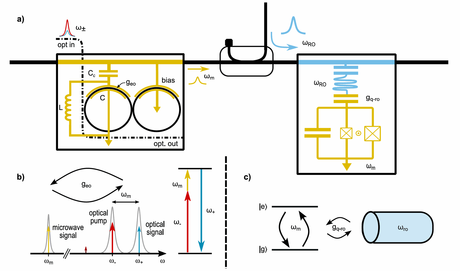
Fig. 1. Transducer-driven superconducting qubit scheme. (a) Two optical fields (ω±) are coupled into the transducer via a waveguide. The two modes are resonant with the transducer’s hybridized optical modes which are generated by a coupled paperclip resonator capacitively coupled (CC ) to a microwave LC resonator. The optical modes interact in the transducer to generate a microwave tone (ωm) via difference frequency generation using the χ(2) nonlinearity in TFLN according to microwave-optical coupling rate geo. The microwave tone is then transmitted to a SC qubit chip via a coaxial cable to drive the qubit through a dispersively coupled readout resonator. We measure the qubit state by measuring the transmission of a readout pulse (ωr o) generated at room temperature. (b) Schematic of cavity electrooptic transduction process. Two hybridized optical modes (ω±) are detuned by the microwave resonance frequency (ωm). Energy exchange between the microwave and optical domains are mediated by the strong pump field at ω−. (c) The qubit computational ground (|g 〉) and excited (|e〉) states are separated by frequency ωm. The qubit is dispersively coupled to a microwave readout resonator (ωro) with strength gq−r o.
Overview
Superconducting qubits are quantum bits based on the superconducting properties of certain materials at extremely low temperatures. They can be manipulated using microwave signals, and their quantum states can be read out by microwave resonators.
While significant progress has been made in improving the coherence and control of individual and small numbers of superconducting qubits, scaling these systems to the size required for complex computations presents a substantial engineering challenge.
The need for cryogenic microwave links between potentially hundreds or thousands of qubits within a large dilution refrigerator becomes increasingly complex, costly, and thermally unsustainable.
To address this, researchers are exploring the possibility of using optical photons as carriers of quantum information between different cryogenic modules.
Optical photons can propagate with low loss through standard optical fibers, even at room temperature, offering a significant advantage over microwave signals which suffer from high attenuation in coaxial cables, especially over longer distances and at higher frequencies, unless cryogenically cooled.
The core of this approach lies in the development of efficient and coherent microwave-to-optical and optical-to-microwave transducers. These devices act as interfaces, converting quantum information encoded in microwave photons (compatible with superconducting qubits) to optical photons (suitable for long-distance transmission) and vice versa.
This research presents the development and characterization of a Cavity Electro-Optic Microwave-Optic Quantum Transducer (CEO-MOQT) fabricated on thin-film lithium niobate (TFLN).
Lithium niobate is a nonlinear optical material that exhibits a strong Pockels effect, a phenomenon where the refractive index of the material changes proportionally to an applied electric field. This electro-optic effect forms the basis of the transduction mechanism.
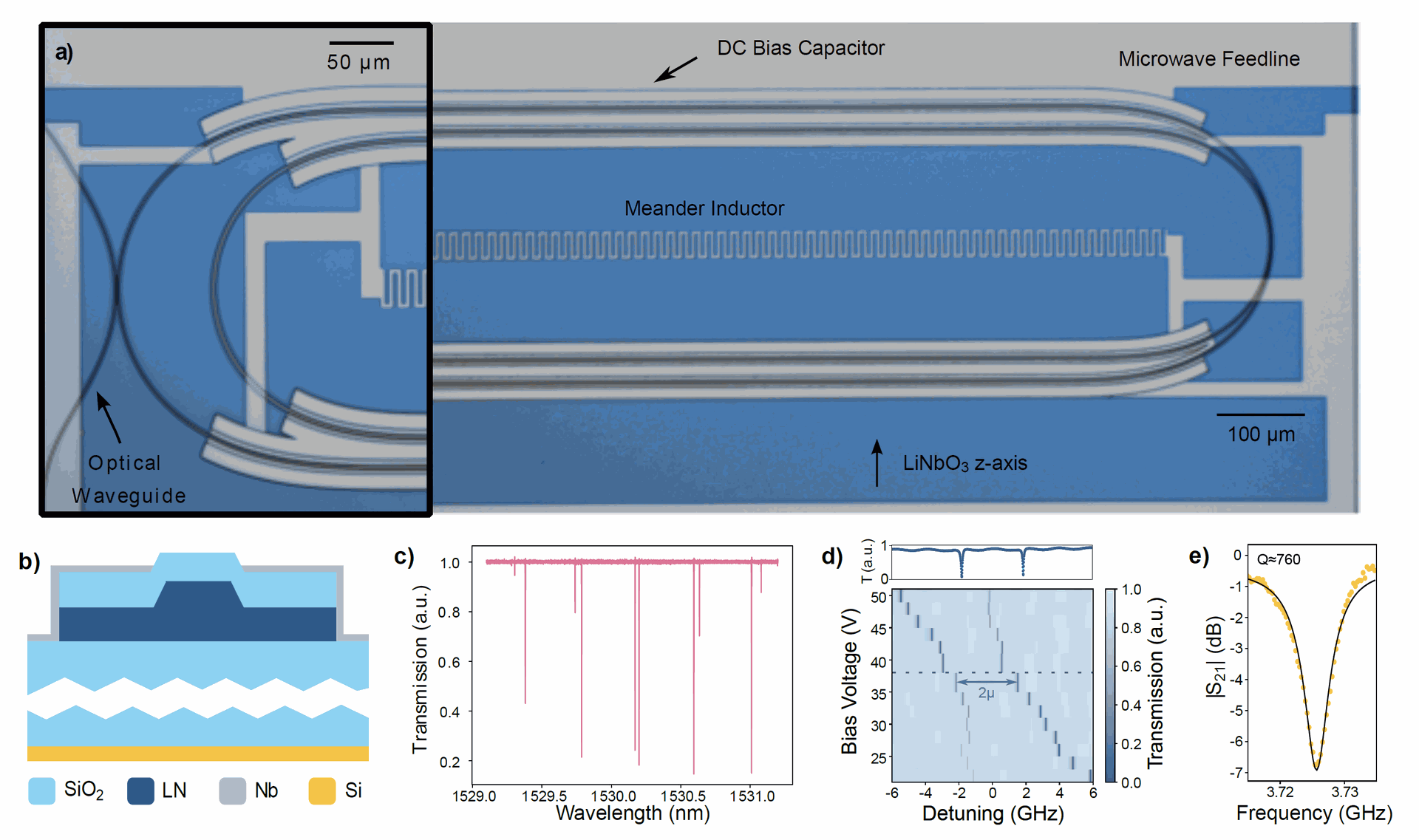
Fig. 2. Cavity electro-optic microwave-optic quantum transducer (CEO-MOQT). (a) Optical micrograph of transducer. A niobium (Nb) microwave LC resonator (silver) is capacitively coupled to two hybridized lithium niobate racetrack resonators in a paperclip geometry (black) to coherently exchange energy between the microwave and optical domains using the resonantly-enhanced electro-optic effect in lithium niobate. This geometry allows us to have a small device footprint to lower parasitic capacitance. The device is cladded with silica to aid with thermal dissipation and mitigate optical losses due to electrical crossovers. The microwave signal is read out via a transmission line (top), and the optical signal is collected via optical grating couplers (See Extended Data Fig. 2). The optical racetrack resonators adiabatically taper from 1 μm in coupling regions to 3 μm in the straight section of the racetrack to reduce sidewall scattering losses while supporting only the fundamental transverse mode (inset). (b) Drawing of device cross-section. Our optical waveguides are gated in a plateau-like electrode geometry to directly contact our Nb electrodes with the z-axis of the LN crystal, thus benefiting from the large Pockel’s coefficient (r33 ≈ 30 pm/V). This improves microwave-optical field overlap, and thus the single photon coupling rate between our microwave and optical modes. (c) The nested paperclip geometry results in a Vernier effect with 5 nm periodicity and ensures the existence of a pair of hybridized optical
modes with splitting similar to the microwave resonant frequency. (d) We can then ensure that we operate at the triple-resonance point by controlling the optical detuning with a voltage bias (2μ ≈ 3.5 GHz) in order to match (e) our microwave resonator frequency (ωm ≈ 3.7 GHz).
The device (illustrated in Fig. 2a) utilizes coupled optical racetrack resonators arranged in a paperclip geometry, which are capacitively coupled to a niobium (Nb) superconducting microwave LC resonator.
The paperclip geometry allows for a small device footprint, reducing parasitic capacitance, a type of capacitor interference. The optical waveguides are designed with varying widths (1 μm in coupling regions and 3 μm in straight sections) to optimize mode confinement and minimize optical losses.
A key feature of the fabrication process is a plateau-like electrode geometry (illustrated in Fig. 2b), where the niobium electrodes are in direct contact with the z-axis of the lithium niobate crystal. This configuration leverages the large electro-optic coefficient of lithium niobate and enhances the overlap between the microwave and optical fields, leading to a stronger single-photon coupling rate.
The transducer operates based on three-wave mixing facilitated by the nonlinearity of TFLN. As depicted in Fig. 1a and 1b, two optical fields (pump) and (idler) are coupled into the transducer.
Through difference frequency generation, a microwave tone is produced, and conversely, a microwave tone can interact with the pump to generate an optical sideband via sum frequency generation.
The triple-resonance condition, where the two hybridized optical modes and the microwave resonator are simultaneously resonant (as shown schematically in Fig. 2d and 2e), is crucial for efficient transduction.
The microwave signal generated by the transducer is then transmitted via a coaxial cable to a superconducting qubit fabricated on a separate chip within the same dilution refrigerator (operating at approximately 15 mK, [- 459.643F] ).
The qubit is dispersively coupled to a microwave readout resonator, allowing its state to be measured by transmitting a readout pulse and analyzing its transmission (schematically shown in Fig. 1c).
Why it’s Important
The ability to coherently interface superconducting qubits with optical photons has profound implications for the future of quantum computing and communication. The successful demonstration of optical control opens the door to modular quantum computing architectures.
Individual superconducting quantum processors, each operating in its own cryostat, could be interconnected via low-loss optical fibers at room temperature, overcoming the limitations imposed by cryogenic microwave links. This modularity could significantly simplify the engineering challenges associated with building large-scale quantum computers.
The microwave-to-optical transducer could also be a key component for realizing quantum networks. Quantum information generated and processed by superconducting qubits can be converted to optical photons and transmitted over long distances through optical fibers to other quantum nodes, potentially enabling distributed quantum computing, secure quantum communication, and the creation of a quantum internet.
This technology could also facilitate the integration of superconducting quantum systems with other quantum platforms that naturally interact with light, such as trapped ions or solid-state emitters. Hybrid quantum systems that leverage the unique strengths of different platforms could unlock new functionalities and applications.
While this research focused on qubit driving, efficient microwave-to-optical transduction can also be used for low-backaction qubit readout. By converting the qubit state information to the optical domain, readout can potentially be performed with less disturbance to the qubit's quantum state.
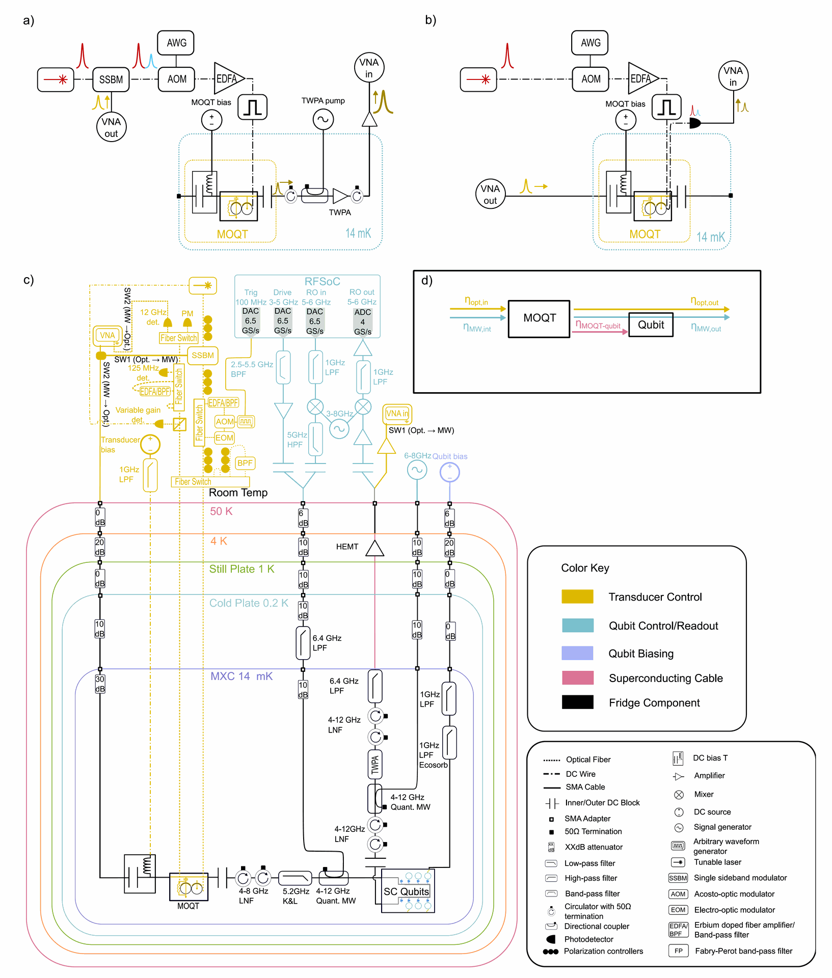
Extended Data Fig. 3. Schematic for CEO-MOQT and SC qubit measurements. (a) Simplified schematic for microwave→optical conversion and (b) optical→microwave conversion. Here, solid lines correspond to electrical cabling and dotted lines correspond to optical fiber. (c) detailed schematic for the whole measurement system. Transducer components are highlighted in gold. Qubit components are highlighted in pink. (d) Definition of link losses (η) in the system.
Summary of Results
The researchers conducted a series of experiments to characterize the performance of the CEO-MOQT and demonstrate its ability to coherently control a superconducting qubit. The math behind the the experiments involves significant quantum mechanics and is beyond the scope of this article but I encourage you to review the math through the publication.
Some technically reduced results of the experiments are:
Transducer Characterization
Bidirectional Transduction Efficiency
The efficiency of converting between microwave and optical signals was measured in both directions (MW→Opt and Opt→MW).
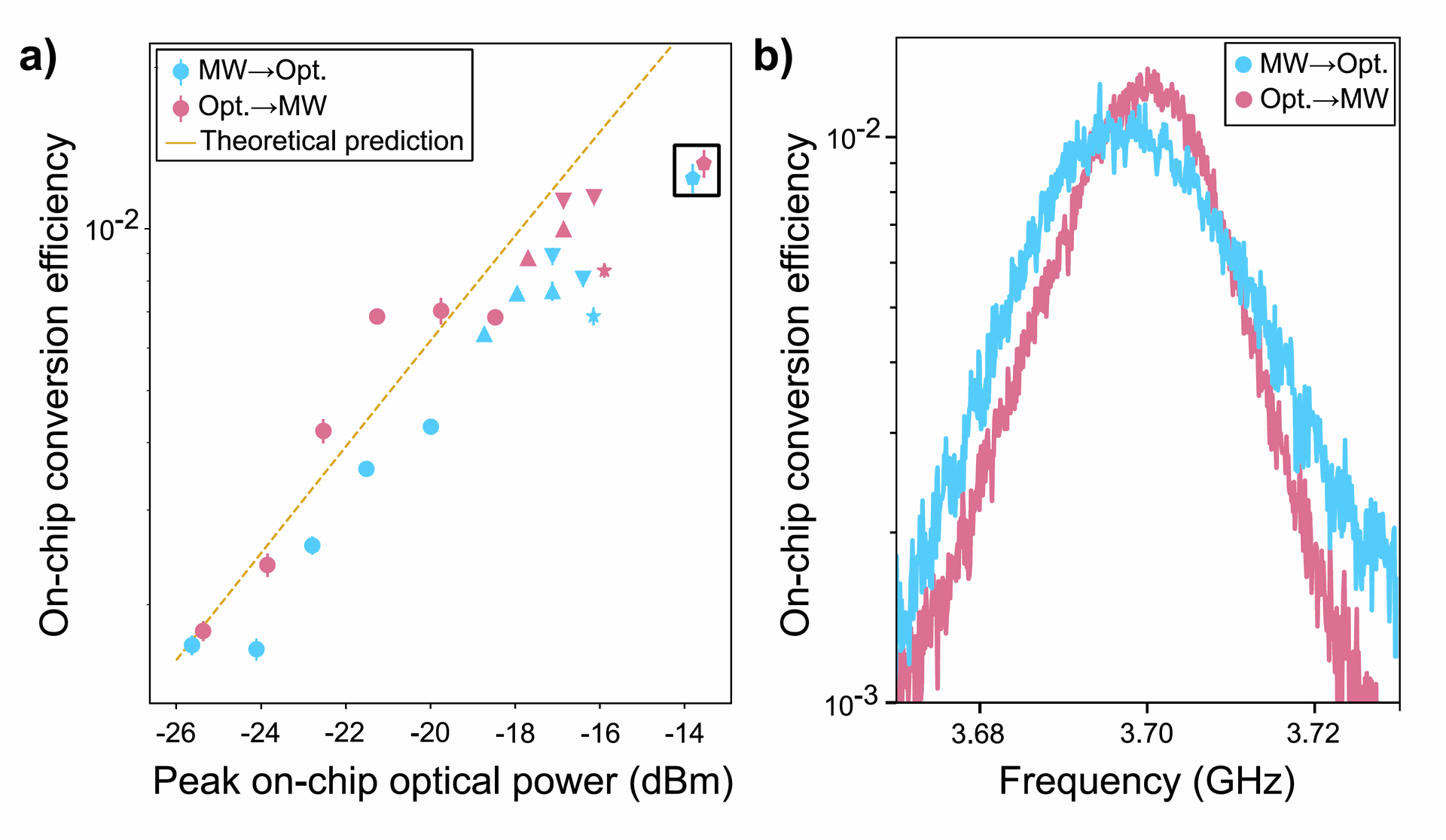
Fig. 3. Characterization of transducer performance. (a) On-chip conversion efficiency for MW→Opt. (blue, sum frequency generation) and Opt.→MW (pink, difference frequency generation) measured for different peak on chip optical pump powers. The roll-off in conversion efficiency is attributed to optical-pump induced quasi-particle generation in our superconductor resulting in excess loss in our microwave resonator and drift away from the triply resonant condition. ◦ markers correspond to CW optical signals, whereas other shapes correspond to a 150 ns pulse with △ 1 MHz repetition rate (15% duty cycle), ▽ 500 kHz repetition rate (7.5% duty cycle), ⋆ 333 kHz repetition rate (5% duty cycle), and D 200 kHz repetition rate (2% duty cycle). The theoretical peak conversion efficiency assuming uniform optical and microwave
loss rates is plotted as a dotted gold line. (b) A frequency-dependent efficiency sweep for a 150 ns pulse with 200 kHz duty cycle is highlighted in the black box in (a).
A peak on-chip conversion efficiency of approximately 1.18% was achieved at an on-chip optical pump power of -13.8 dBm (44.2 μW). The transducer also exhibited a bidirectional 3dB bandwidth of up to 30 MHz (Fig. 3b), indicating its capability for relatively fast operations.
The efficiency per microwatt of pump power in the linear regime was found to be (%η/µW = 0.05). This high efficiency is attributed to the enhanced electro-optic field overlap achieved with the plateau electrode geometry. Figure 3a shows the on-chip conversion efficiency for different peak on-chip optical powers and duty cycles in pulsed mode.
Microwave-Optical Coupling Rate and Cooperativity
From efficiency and linewidth measurements, the microwave-optical single-photon coupling rate geo/2π was extracted to be approximately 945 Hz, and the cooperativity (C) reached up to 1.16%. The cooperativity (C) provides insight into the coherence of the system.
Added Microwave Noise
The amount of microwave noise generated by the transducer due to the optical pump was carefully evaluated using a Real-Time Spectrum Analyzer.
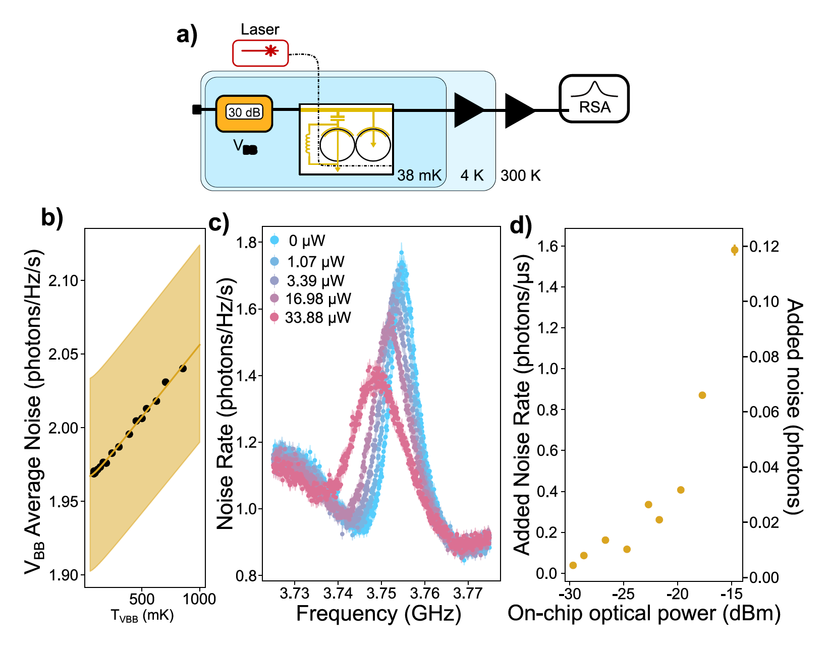
Fig. 4. Evaluation of optically generated microwave noise in the transducer. (a) Measurement schematic. We send a continuous-wave (CW) optical pump to the transducer and measure the power spectral density (PRSA) of the microwave signal generated on superconducting electrodes on a radio spectrum analyzer (RSA) with a 1 kHz resolution bandwidth (RBW) averaging over 200 measurements. We note that the microwave signal is amplified using 4K and 300K amplifiers. We calibrate the link gain in the system using a variable temperature black-body source (VBB ) that is weakly thermalized to the mixing chamber plate22. (b) Calibration curve for the average output noise photon rate per
hertz bandwidth of the VBB (black dots) that allows us to extract the link gain (G) and system added noise rate (Nsys ) according to equation 1. The line of best fit is plotted in gold. The fit uncertainty is shaded. (c) Power spectral density (PSD) emitted by the device and converted into noise photon rate. Error bars correspond to calibration uncertainty. The PSD measured with the laser beam blocked is plotted in blue. (d) Added noise rate per microsecond (left axis) and noise photons emitted by the resonator during the resonator lifetime (right axis) for a given CW pump power. The error bars correspond to the uncertainty due to calibration errors plotted in (b).
As shown in Fig. 4, the added noise rate was found to be less than 0.12 photons for on-chip optical powers up to 33 μW.
This low added noise is crucial for preserving the quantum coherence of the qubit. Figure 4a shows the measurement schematic for noise evaluation, 4b depicts the calibration curve for noise measurements, 4c presents the power spectral density emitted by the device, and 4d shows the added noise rate and noise photons emitted over the resonator lifetime as a function of pump power.
Coherent Qubit Control
Continuous-Wave Spectroscopy
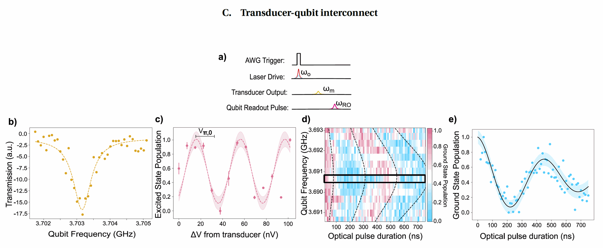
The transducer was used to generate a weak continuous-wave microwave signal at its resonant frequency, which was then sent to the superconducting qubit. By sweeping the qubit's frequency using a flux bias, a clear spectroscopic response was observed (Fig. 5b), indicating that the optically generated microwave signal could drive transitions in the qubit.
In essence, CW qubit spectroscopy served as a fundamental step to establish a working link between the optical transducer and the superconducting qubit, enabling the verification of signal transfer and the determination of key operating parameters
Pulsed Rabi Oscillations
To demonstrate coherent control, pulsed optical signals were sent to the transducer, generating corresponding microwave pulses that drove Rabi oscillations in the qubit. Rabi oscillations are periodic flips of the qubit's quantum state between its ground and excited states, driven by a resonant signal.
Figure 5a shows the pulse sequence used for these measurements. Both power Rabi oscillations (sweeping the power of the optical idler while keeping the pulse width constant at 100 ns, Fig. 5c) and time Rabi oscillations (sweeping the width of the optical pulses at fixed power, Fig. 5d and 5e) were observed.
A Rabi pulse that flips the qubit's state with high probability was achieved. From the RFSoC time Rabi oscillations, a Rabi frequency of 2.27 MHz was measured at the transducer frequency. The chevron pattern observed in Fig. 5d, where the qubit's detuning from the driving frequency is swept, further confirms coherent control.
Transducer-Qubit Link Loss
By comparing the measured Rabi frequency with the expected Rabi frequency based on the estimated microwave power emitted by the transducer, the researchers estimated a link loss of approximately 2.67 dB (46%) between the transducer and the qubit. This loss is attributed primarily to microwave losses in the cables, circulators, filters, and directional coupler in the cryogenic setup.
Conclusion
This research successfully demonstrated the coherent optical control of a superconducting qubit using a high-efficiency, low-noise electro-optic transducer based on thin-film lithium niobate.
The developed CEO-MOQT exhibited promising performance, including high bidirectional conversion efficiency, broad bandwidth, strong microwave-optical coupling, and low added noise.
The ability to drive Rabi oscillations in a superconducting qubit with a microwave signal generated from an optical source represents a significant step towards realizing modular and scalable quantum computing architectures by enabling the use of low-loss optical links between cryogenic quantum processors.
Future efforts will focus on reducing microwave losses in the system and further optimizing the transducer design to enhance its performance and fidelity for quantum information transfer.


Paving the Way for Room Temperature Quantum Information Exchange
Coherent Control of a Superconducting Qubit Using Light